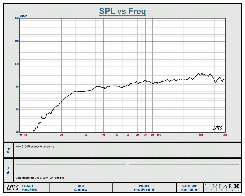
Check out the 3 Pi sub's performance graph.
The measurement shows frequency response in the horizontal and
amplitude in the vertical axis. This measurement is what is called a
"ground-plane" measurement. That means the measuring mic is placed on
the floor at a distance from the sub, with the sub also being on the
ground. Additionally, the measurement is done out-doors. This method
gives essentially a reflection-free response -- no echoes or bounces from
any surface. In terms of frequency response, that's like measuring the speaker in theoretical free
space, so you can actually see what the sub is putting out, by itself.
We do this because normal sized listening rooms will interfere with the
output of the sub at different frequencies as measured at the microphone. You will get all sorts
of phase cancellations and "room effects." Since those effects are
different in different sized rooms, we need to eliminate the room from
the measurement to have a performance baseline.
Here's something interesting. Trace the graph from
40Hz down to 20Hz. There is about a 6dB rolloff in amplitude in that
octave. Typically, when you place a speaker in a room it will gain 6 or
more dB per octave descending in frequency response. Therefore the 3 Pi
sub in most rooms will actually provide
flat response down to 20Hz. So the design takes into consideration that "room-gain" gets you flat performance down to 20Hz, which is all you need.
The
other end of the sub's frequency range, typically determined by low
pass filters incorporated in the plate amplifier built into the sub, is
variable. You wouldn't normally use it as high as 200Hz. If the sub is
far away from the main monitors, 50-80Hz is good. If it is close or
flanks the mains, a higher low pass may be used, up to 150Hz or so, if
used in stereo pairs along side and behind the mains.
As an update, here are shots of the 3 Pi subwoofer we made with the
final touch added, "grotesque industrial (truck bed liner) black." Yep, I
preferred the naked look, 20-20 hindsight and all... We could have
simply given it a nice tung oil finish, the wood has excellent grain,
but this has a certain
dreadnaught appeal. At least we completed
the project as planned. ; ) The sound is as magnificent as it was during
the Earpocalypse, performance down to 20Hz. Final touch:
Pi Subwoofer Project Part 3 here!


Well, a friend of mine gave me a prototype chipset he developed for an RDAC, a Resistive Digital-to-Analog Converter. That is in English, a digitally controlled potentiometer. This can be used as the basis for an audio preamp. It has provisions for metering, control circuitry (power switching), relay controls, LED indicators, and 2 additional redundant RDACs -- one could be used for controlling a subwoofer output, another for VU meters, etc. I have designed a power supply and bought all the components, excepting the chassis. Mine will have LED VU meters. Forgot to mention, the chipset includes infra red remote control functionality. So you can switch inputs; CD, computer. TV, whatever, and control volume via a universal remote.
ReplyDeleteWhy is the RDAC good?
It is a pure signal path, 100% analog path, but digitally controlled. Remember that all potentiometers are mechanical devices, they get dirty, scratchy, eventually the stereo versions do not track evenly, left and right, etc.. The RDAC has no mechanical issues. Freedom from noise plus analog path. Perfect. I might start a new thread on this, just so I can show off my panel design. If you see that, then it might become a group project.
Hey, I edited the post adding a bunch of stuff, including performance measurements and explanations. Enjoy!
ReplyDeleteHi Vin, Where are you?
ReplyDeleteHernan, I couldn't find my login credentials for this ancient blog until the magic of old hard drive backups revealed a dusty username and password. Miss you guys. Now that I can log in, I may use this again.
Delete